-
Pests and disease incident on the crops / plants are to be overcome by the application of poisonous chemicals.
-
As the technology advances and newer crop varieties are introduced newer insects, pests and diseases are also growing up and methods are deviced to control them.
-
Many chemicals used for plant protection cannot be handled by human operators directly.
-
Also, that needs to be applied in fine particles.
-
This necessitates the use of suitable machines.
Sprayers
-
The Sprayer is one which atomises the spray fluid (which may be a suspension, an emulsion or a solution) into a small droplets and eject it with little force for distributing it properly.
-
It also regulates the amount of pesticide to avoid excessive application that might prove wasteful or harmful.
-
The mechanical appliances that are used for distributing the dust formulations of pesticides are called as dusters.
Types of sprayers
-
Sprayers are classified into four categories on the basis of energy employed to atomise and eject the spray fluid as
-
hydraulic energy sprayer
-
gaseous energy sprayer
-
centrifugal energy sprayer and,
-
kinetic energy sprayer
Hydraulic energy sprayer
-
Hydraulic Energy Sprayer is one which the spray fluid is pressurised either directly by using a positive displacement pump or by using an air pump to build the air pressure above the spray fluid in the air tight container.
-
The pressurized fluid is then forced through the spray lance, which controls the spray quantity and pattern.
Gaseous energy sprayer
Centreifugal energy sprayer
-
In the Centrifugal Energy Sprayer the spray fluid fed under low pressure at the centre of a high speed rotating device (Such as flat, concave or convex disc a wiremesh cage or bucket, a perforate sieve or cylinder or a brush) is atomised by centrifugal force as it leaves the periphery of the atomiser.
-
The droplets are carried by the air stream generated by the blower of the sprayer or by the prevailing wind, if the sprayer is not provided with a fan.
Kinetic energy sprayer
Types of sprayers
-
Depending on the source of power it can be classified as manually operated and power operated dusters.
-
The manually operated dusters are (i) package duster (ii) plunger duster (iii) bellow duster and (iv) rotary duster.
(i) Package dusters
-
In some pesticide dusts are packed in containers that serve as a hand applicators and may be discard after use.
-
They are mostly provided with rubber, leather or plastic section which, on getting squeezed, provides a puff of air that emits the dust in a small cloud.
-
The simplest type of package duster is worked by pressing it between the fingers.
(ii) Plunger dusters
-
The consists of an air pump of the simple plunger type, a dust chamber, and a discharge assembly consisting of a straight tube or a small exit pipe whose discharge outlet can be increased or decreased by moving a lid provided at the end of the dust chamber.
-
The air from the pump is directed through a tube into the container where it agitates the dust and eject it from a discharge orifice or tube.
-
The amount of dust can be controlled by the speed of the operation of the pump.
-
These are useful for spot application in restricted areas and for controlling ants, poultry pest and pest of farm animals.
(iii) Bellow duster
-
In the below may be made from rubber, leather or plastic.
-
On squeezing, it puffs the air that expels the dust in a small cloud.
-
Hand held bellow duster has containers of capacity from 30 g to 500 g.
-
The bellows can be operated either directly by hand or by handle provided for that purpose.
-
The knapsack duster has the container capacity of 2.5 to 5.0 kg.
-
The air blast developed by the bellow draws the dust from the hopper and discharges through the delivery spout intermittently.
-
These dusters are suitable for spot treatments.
(iv) Rotary duster
-
A consists basically of a blower complete with a gear box and a hopper. It is operated by rotating the crank.
-
The cranking motion is transmitted through the gear box to the blower.
-
A drive is taken for the dust agitator located in the hopper.
-
The rotary duster may be hand carried type or shoulder mounted or belly carried type.
-
The feed is controlled by a feed control lever, which operates a slide to control the aperture at the bottom of the hopper.
Some of the recommendation of WHO (1974) for this duster are
-
The sheet hopper should not be less than 0.63 mm thick.
-
The concave bottom of the hopper permits all the dust to move towards the feeding aperture.
-
The fan should be capable of displacing 0.84 m3 of air per minute at a speed of 35 rpm.
(v) Power dusters
 |
-
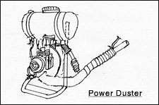
The resemble the rotary duster is construction, except that the power to drive the blower through the gear box is tapped from an external power source which may be an engine or P.T.O. shaft of the tractor or flywheel of the power tiller.
-
The power operated centrifugal energy knapsack sprayer also can be converted into a power duster, by allowing the dust fluid into the air stream, near the point of attaching the pleated hose, in the blower elbow.
|
Uses of spraying and dusting equipments
-
The spraying and dusting equipments are used for the following purposes
-
For the insecticides application to control insect pests on crops and in stores, houses, kitchen, poultry farms, barns, etc.
-
For the insecticides application to control insect pests on crops and in stores, houses, kitchens, poultry farms, barns, etc.
-
For the acarices application to control phytophagous mites.
-
For the fungicides and bactericides application to control the plant diseases.
-
For the herbicides application, to kill the weeds.
-
For the harmone sprays application to increase the fruit set or to prevent the premature dropping of fruits.
-
For the application of plant nutrients as foliar spray.
-
For applying the powdery formulation of poisonous chemicals on the crops and for any other purposes.
Hand sprayer
 |
-
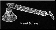
The hand sprayer is a small, light and compact unit.
-
The capacity of the container varies from 500 to 1000 ml.
-
This is generally used for spraying small areas like kitchen garden and experimental laboratory plots.
-
It is a hydraulic energy sprayer.
-
It has a hydraulic pump inside the container, with cylinder, plunger and a plunger rod.
-
By operating the plunger up, the spray fluid in the container is sucked into the cylinder through a ball valve assembly and then pressurised during the downward stroke.
|
-
The pressurised fluid is then let out through a nozzle, and sprayed into fine droplets.
-
If the pressure to be built inside the container an air pump with cylinder, plunge and plunger rod is required.
-
When the plunger is pulled up, the air is sucked into the cylinder and when pushed down the air bubble is releases into the container with 80% of its volume filled with the fluid.
-
The air reaches the space above the free fluid surface and presses the fluid.
-
The pressurised fluid is drawn up through a trigger cut of valve to the nozzle, where is atomized and sprayed.
-
In some other type, air pump and the container are separate pieces and the pump is attached to the container is such a way to release the pressurised air through an orifice at the top of the container.
-
The fluid is lifted through an office at the top of the container.
-
The fluid is lifted through a capillary tube due to surface tension developed by the high velocity air at the outlet and sheared away by the air and sprayed as droplets.
Knapsack sprayer
  |
-
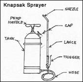
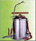
Any sprayer which is carried on the back of the operator is called a knapsack sprayer.
-
The commonly used manually operated knapsack sprayer will have one hydraulic pump working inside the container.
-
The plunger works inside the replacement well attached at the bottom of the container, for easier maintenance.
-
The pump can be operated through the appropriate linkages by oscillating the handle, with the sprayer carried on the back.
|
-
An agitator is also provided with the pressure chamber to agitate the fluid so that the particles in suspension will not be allowed to settle down.
-
A delivery tube is attached on the other end of the pump which carries the pressurises fluid to the spray lance.
-
The flow to the nozzle is controlled by a trigger cut-off valve.
-
In the case of compression knapsack sprayer, an air pump is used to build air pressure above the free surface of the spray fluid in the container and normally the pumping of the air will be done by keeping the unit on ground and then sprayed til the air pressure comes down.
-
The unit is again brought back to the ground for pumping air and then the spraying is contained as before.
-
The spray fluid, which does not enquire any agitation only can be sprayed by using this type of sprayers.
Rocker sprayer
  |
-
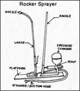
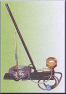
The rocking sprayer has a pump assembly, fixed on a wooden platform with an operating lever, a valve assembly with two ball valves, a pressure chamber, suction hose with strainer, and delivery hose with spray lance.
-
When the plunger is pulled behind by pulling the lever way from the pump, the spray fluid from the container is sucked through the strainer and pushes the bottom ball valve above and enters the pump.
-
The movement of the lower ball valve is arrested by the upper valve seat.
-
When the lever is pushed towards the pump, the sucked fluid is forced to enter the pressure chamber by opening the upper ball valve.
|
-
The operation is continued till the entire suction pipe, ball valve assembly, delivery hose and a portion of pressure vessel is fitted with spray fluid and the pump operator finds it difficult to push the piston forward, due to the downward pressure developed by the entrapped compressed air in the pressure vessel.
-
Thereafter, the trigger cut off valve will be opened to allow the spray fluid to rush through the nozzle and get atomized.
-
Usually 14 to 18 kg/cm2 pressure can be built in the pressure chamber and hence can be conveniently used for free spraying.
Bucket sprayer
 |
-
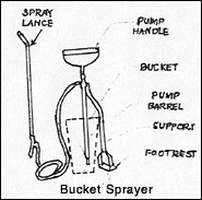
The bucket sprayer is designed to pump the spray fluid directly from, the open container, usually a bucket.
-
The hydraulic pump will be put inside the bucked and held properly with the help of foot rest.
-
As the plunger is pulled up, the fluid enters through the suction ball valve assembly and when the plunger is pressed down, the suction valve closes and the fluid enters the pressure chamber through a ball valve assembly.
-
As the plunger is continuously worked, pressure is built in the pressure chamber and the delivery hose.
-
As soon as the required pressure is built up, the spraying will be done.
-
A pressure of 4 kg / cm2 is developed in most of the models.
|
Foot sprayer
  |
-
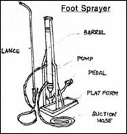
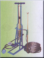
This is a modified version of rocker sprayer.
-
The pump is fixed in a vertical position with necessary braces.
-
The plunger moves up and down when operated by the pedal.
-
A ball valve is provided in the plunger assembly itself to allow the fluid to cross the plunger and getting pressurized in the pressure vessel.
-
During the upward motion of the piston fluid is sucked in and pressurized into the pressure vessel and during downward movement, the sucked fluid crosses the plungers and enter the pump.
-
The pressure developed is about 17-21 kg/cm2.
|
Power sprayer
  |
-
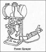
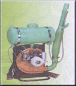
All the sprayers which impart the mechanical energy developed by an I.C. Engine, on the spray fluid before spraying is called as a power sprayer.
-
The most commonly used type of power sprayer in India is a gaseous energy type knapsack sprayer.
-
In construction, it has a back pack stand on which a blower with a S.I.
-
Engine of 1.2 to 3 hp capacity, the spray fluid tank and the petrol tank are fixed rigidly.
-
A pleated hose is attached to the blower elbow to carry the high velocity air and at the end of that a shear nozzle is fixed to allow the spray fluid to trickle in from the spray fluid storage tank, with a valve control.
|
-
From the top of the blower casing, an air hose is taken into the spray fluid tank, which carries little quantum of air to press the spray fluid during operation.
-
In operation, the engine is started by keeping the unit on the ground and then carried by the operator.
-
The blower sucks the air behind the backrest and forces it into the pleated hose.
-
The valve of the shear nozzle is opened or the shear nozzle with selective opening and discharged through the nozzle.
-
The high velocity air shears off the droplets and atomizes by the impact of diffuse and delivers it on the plant the surface.
-
An air current of 2.7 to 9.1 m2 / minute is delivered at a velocity of 175 to 320 kmph.
-
The spray fluid tank capacity varies from 7 to 12 litres.
-
The fuel tank capacity varies from 0.75 to 2.25 litres.
-
The spray fluid discharge can be varied from 0.5 to 5 lit / minute.
A power sprayer can be used as a power duster by making the following changes.
-
Chemical filler cap is removed to dismantle that strainer with the air pipe.
-
The liquid delivery pipe below the chemical tank is dismantled and removed with the shear nozzle.
-
The tank is thoroughly cleaned to remove possible traces of moisture left inside.
-
The dust agitator tube is fixed at the bottom of the chemical tank.
-
This tube has holes at the bottom to prevent the entry of dust into the agitator and clogging it.
-
Dust intake tube is inserted into the chemical tank at the discharge and this tube has no. of large size holes on its periphery.
-
Dust intake tube and the blower elbow are connected by using the dust outlet pipe, which is a pleated hose.
Battery or ULV sprayer
 |
The basic requirements of ULV spraying are
-
The narrow and controllable droplet spectrum (100-250 µm for fine sprayers, 50-100 µm for mist sprayers and 0.1 to 50 µm for aerosols)
-
The accurately controllable emission rate and
-
The non-volatile pesticide formulation of suitable viscosity and density.
|
-
The reduction in volume of the spray fluid decreases the time spent in travelling to recharge sprayer, in fetching water, in mixing the pesticide and filling the tank. In a day of 8 hour about 8 ha can be covered in ULV spraying against 3 ha with power sprayer.
-
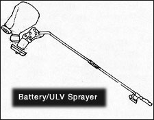
A battery operated ULV sprayer has a long handle at the horse power D.C. motor is fitted with a spinning disc and a cover.
-
A HDPE bottle is fixed close to the motor, in such a way that spray fluid is allowed to trickle at the centre of the spinning disc in operation.
-
Centrifugal energy imparted fluid comes out of the nozzle and atomizes.
-
The hand held ULV applicators are so designed to release the spray droplets at 1 m away from the body of the operator.
-
Further, it is recommended that they should be operated only when the spray cloud would be blown away from him by the breeze so as to minimize the risk of contamination.
-
After spraying, the atomizer must be flushed with paraffin to remove the residual pesticide.
-
Inefficient cleaning would leave the pesticide deposit in the feeder stem to completely of partially block the flow of the pesticide.
Power sprayer operated suction trap
-
This consists of a metal elbow matching the suction opening and the blower and the outer diameter of the pleated hose.
-
This unit is closely fitted with the blower suction opening with the help of an extension frame work identical to the back pack stand.
-
To the pleated hose attachment opening of the elbow a pleated hose is attached rigidly.
-
In between the two pleated hoses a screen, an insect collector and valve to control the size of the opening are provided in a Tee section.
-
In operation the low pressure created at the blower inside is transmitted through the below and pleated hose which helps in sucking the lighter objects like insects and dust from a distance of 0.5 to 1.0 m away from it.
-
The sucked insect of dust will be filtered by the screen and dropped into the collection bowl.
-
Drain off any liquid still in the tank.
-
Add 1 kg of washing soda per 45 litres of water, which will serve as a cleaning detergent.Spray this liquid through the nozzle on waste land.
-
Add fresh water in the tank and spray with and then without nozzle on the waste land.
-
Wash the outside of the sprayer.Remove the nozzle and filters and store safety after cleaning.
-
Ensure the absence of water in the pump and lubricate the parts.
|


